

 September 5, 2026
Building a Complete Humsienk 8 kW Hybrid System From Scratch

Notes:
This article comes from Luis, the engineer behind AMS Lab, an independent workshop covering engineering builds, infrastructure, and board-level repair. Luis picked up a Humsienk 8 kW hybrid inverter and 5.12 kWh LiFePO4 battery with no shortcuts in mind: he built his own distribution and protection box from scratch, documented every wiring decision, and ran into a real configuration problem along the way, then worked through it until the system operated the way it should.
We're republishing his full write-up here, with his permission, exactly as he documented it. If you're planning your own installation, this is the kind of ground-level detail a spec sheet can't give you: what a proper protection setup looks like, what a Same Phase configuration error actually presents as, and how to confirm your system is working correctly once it's built.
You can find Luis's original article and his full video series at AMS Lab's blog.
Humsienk Real Application Testing
Luis set out to do more than plug in an inverter and battery and call it done. His first mini-series follows the entire process of assembling, configuring, and testing a Humsienk hybrid setup — an 8 kW inverter paired with a 51.2V, 100Ah LiFePO4 battery. As he put it, he wanted a test installation that could reveal how the system behaves, how its protections should be organized, how it hands off between grid and battery power, and what happens when a configuration step doesn't go right on the first try.
The Hardware Behind the Build
The setup centered on a Humsienk 8 kW hybrid inverter and a 51.2V 100Ah Humsienk LiFePO4 battery, good for roughly 5.12 kWh of usable storage. The battery's BMS communicates with the inverter over CAN/RS485, and the system supports 120/240V operation with photovoltaic input, a built-in automatic transfer switch, and remote monitoring through a communication dongle paired with the SOLARMAN App.
- Humsienk 8 kW hybrid inverter
- 51.2 V / 100 Ah Humsienk LiFePO4 battery
- Approximately 5.12 kWh of energy storage
- CAN/RS485 battery-management communication
- 120/240 V operation, PV input, internal ATS, and SOLARMAN monitoring
Building a Distribution and Protection Box
Before wiring anything into the inverter, Luis built a standalone distribution box to keep the incoming utility feed, the inverter's input and output, connected loads, isolation points, a bypass path, and monitoring organized in one place. His build videos walk through conductor prep, terminal choices, ferrules, and the reasoning behind the layout rather than just showing a finished panel.
This project documents my test installation and is not a substitute for a qualified electrician. Conductor size, breakers, and protection must be calculated for each installation and its real current. The deliberately limited test loads used here do not mean 12 AWG can support the inverter's full 8 kW output.
Adding a Standalone Solar Protection Module
The eventual solar input got its own dedicated protection, housed in an eight-space DIN enclosure: a two-pole DC breaker, two-pole DC surge protection, a pair of 20A photovoltaic fuses, and MC4 connectors on both ends of the run between the panels and the inverter's PV input. The series covers the internal layout, terminal choices, and enclosure modifications needed to fit it all together.
Taking a Close Look at the Inverter and Battery Before Installation
Before installation, Luis unboxed and inspected each unit on its own. The inverter came with CT clamps, a communication dongle, wall-mounting hardware, battery terminals, documentation, and a cable for linking multiple inverters together. The battery — a wall-mounted 5.12 kWh LiFePO4 unit — got the same treatment: its conductors, BMS cable, ports, and the CAN/RS485 configuration that lets the inverter read more than just raw voltage, giving it real visibility into the battery's actual state.
Wiring the Grid, Inverter, and Loads Together
The test wiring path ran from the utility grid into the distribution box, into the Humsienk inverter's AC input, back out through the AC output, through the distribution box again, and finally to the loads. At this stage, output was routed to a single receptacle standing in for the loads a completed installation would eventually support, with every connection kept visible and serviceable rather than buried inside the enclosure.
The Problem That Made This Build Worth Documenting
Running on battery alone, everything worked as expected — the inverter powered its loads without issue. Grid behavior was a different story. Input detection, bypass switching, and charging from the grid all failed to behave correctly, which sent Luis digging into the wiring, the inverter's grid settings, L1/L2 behavior, its Same Phase mode, and BMS communication. Documentation for this exact scenario was hard to find, which is exactly why he decided to write the fix up in detail.
Solving It With the Same Phase Setting
The root cause turned out to be his bench power source itself: it wasn't delivering standard 120/240V split-phase power the way a typical home service would. For that specific setup, the inverter needed its Same Phase setting configured correctly, along with a matching L1/L2 connection, before it would recognize the incoming power at all. Once that setting matched his actual source, grid detection, bypass, battery charging, and automatic transfer all started working.
He's careful to note this isn't a general instruction to bridge L1 and L2 in any installation. A genuine 120/240V split-phase service uses those two legs differently, and any configuration has to match the actual power source, the manufacturer's documentation, and local electrical code.
Putting Automatic and Manual Transfer to the Test
With grid operation sorted, Luis tested the inverter's built-in automatic transfer switch by cutting utility power live and watching the battery pick up the load without interruption. He also added a manual transfer path inside his distribution box — a physical bypass option that let him confirm exactly which source was powering the system during any given test.
Bringing the System Online With SOLARMAN
The last piece of the build connected the communication dongle and linked the inverter to the SOLARMAN app, giving Luis remote access to the inverter's and battery's operating data — a way to check on the system without needing to be standing in front of it.
Where the Build Ended Up
What started as an inverter, a battery, and a pile of components ended up as a fully working hybrid test system, with documented fixes for every problem that came up along the way. By the end, the setup powered loads from roughly 5 kWh of stored energy, correctly detected grid input and charged from it, verified both automatic and manual transfer, had protection ready for a future solar input, and had working BMS and SOLARMAN monitoring in place.
- Powered loads from approximately 5 kWh of LiFePO4 storage
- Detected grid input and charged the battery
- Verified bypass and automatic ATS transfer
- Added a manual transfer path
- Prepared protection for a future photovoltaic input
- Established BMS communication and SOLARMAN monitoring
What This Build Confirms About the 8 kW Hybrid System
Luis's test installation reflects exactly how we designed this system to behave: an internal ATS that hands off between grid and battery without manual intervention, CAN/RS485 communication that gives the inverter real visibility into battery status rather than just voltage, and a Same Phase setting built specifically for situations like his, where the incoming power source isn't standard 120/240V split-phase.
If you're planning a similar build, a few things from his notes are worth carrying into your own project:
- Grid configuration matters before anything else. If your inverter isn't detecting input the way you expect, check the Same Phase and L1/L2 settings against your actual power source before assuming a hardware issue.
- A dedicated distribution and protection box isn't optional. It's the difference between a system you can safely troubleshoot and one where every problem means guesswork.
- SOLARMAN monitoring is there to be used. Remote visibility into inverter and battery data catches issues before they become failures.
Full specifications for the 8 kW hybrid inverter and 5.12 kWh LiFePO4 battery Luis used in this build are available on our product pages, and our support team is available if you run into a configuration question of your own.
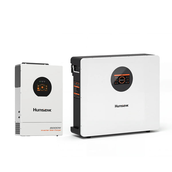
8kW Hybrid Inverter + 48V 100Ah LiFePO4 Battery
Comments
-
Me gusta mucho la marca humsienk,construyen equipos de mucha presencia y calidad
Leave a comment
Your email address will not be published. Required fields are marked *

 October 20, 2026


